
CUnet
Summary
CUnet is a multiple-master remote I/O control network that can control digital I/O, analog I/O, and positioning control. Up to 64 ICs can be connected and up to 512 bytes of data can be shared in I/O control. CUnet offers a simple and low-cost way to use serial communication not only for DIO control, but also analog control, previously dependent on parallel connection.
Also, for motor control within a device, CUnet (MKY44MC series) can control positioning using an I/O level network, as long as it is within a certain range. Thus, CUnet (MKY44MC series) makes it possible to switch a control point that used to use expensive motor drivers and servomotors to an affordable and appropriate configuration.
The point of CUnet as a network is:
If you can do it with an I/O level network, do it!
CUnet offers I/O control in devices with appropriate cost, appropriate speed, and appropriate noise immunity.
"CUnet Introduction Guide" and "CUnet technical Guide", "Let's Try CUnet" can be downloaded here.
CUnet network devices
Learn about our devices for building CUnet networks.
| Series name | MEM mode IC (master/slave) |
MEM mode IC (master/slave) |
IO mode IC (DIO slave) |
IO mode IC (DIO slave) |
|
|---|---|---|---|---|---|
| Type | MKY43 | MKY44-SPI | MKY46 | MKY44-IO32A | |
| Package |
 |
 |
 |
 |
|
| Function | Data (memory) sharing | Data (memory) sharing | 32 DIN/DOUT | 32 DIN/DOUT with filter 2 ch 24 bit up/down counter (encoder) 2 ch 16bit PWM output |
|
| Supply voltage | 3.3 V (5 V tolerant) | 3.3 V | 5.0 V | 3.3 V | |
| Features | Support mail function (256-byte data transmission) Support 16/8 bit bus interface. |
Support mail function (256-byte data transmission) Support SPI interface. |
No CPU is required 32 DIN/DOUT switchable in 4 bits |
No CPU is required 32 DIN/DOUT switchable in 4 bits ST44SW: Required |
| Series name | IO mode IC (AD slave) |
IO mode IC (AD slave) |
IO mode IC (AD slave) |
IO mode IC (DA slave) |
IO mode IC (DA slave) |
|---|---|---|---|---|---|
| Type | MKY44-AD12A | MKY44-AD16A | MKY44-AD16B | MKY44-DA16A | MKY44-DA16B |
| Package |
 |
 |
 |
 |
 |
| Function | 12 bit AD 4ch 4 DIN/4 DOUT |
16 bit AD 2ch 8 DIN/8 DOUT |
16 bit AD 4ch | 16 bit DA 2ch 8 DIN/8 DOUT |
16 bit DA 4ch |
| Supply voltage | 3.3 V | 3.3 V | 3.3 V | 3.3 V | 3.3 V |
| Features | No CPU is required Built-in AD converter ST44SW: Unrequired |
No CPU is required External AD converter (AD7682) ST44SW: Required |
No CPU is required External AD converter (AD7682) ST44SW: Unequired |
No CPU is required External DA converter (AD5752) ST44SW: Required |
No CPU is required External DA converter (AD5754) ST44SW: Unequired |
| Series name | IO mode IC (positioning slave) |
IO mode IC (positioning slave) |
IO mode IC (slave) |
HUB-IC | Support IC | |
|---|---|---|---|---|---|---|
| Type | MKY44-MC01A | MKY44-MC02A | MKY44-FS00A | MKY02 | ST44SW | |
| Package |  |
 |
 |
 |
 |
|
| Function | 24 kpps motor control 1 axis Rotary encorder input 1 ch general-purpose DI/O |
12.5 kpps motor control 2 axis Rotary encoder input 2 ch general-purpose DIO |
Acceleration of communication among I/O |
― | SA, DOSA, BPS pin expansion for some MKY44 series chips |
|
| Supply voltage | 3.3 V | 3.3 V | 3.3 V | 3.3 V (5 V tolerant) | 3.3 V | |
| Features | No CPU is required Trapezoidal velocity control (Acceleration and deceleration: linear or S-curve) No inter polation function ST44SW: Required |
No CPU is required Trapezoidal velocity control (Acceleration and deceleration: linear or S-curve) No interpolation function ST44SW: Required |
Supports communication among ICs in I/O mode |
No CPU is required T-type branching and wiring extension possible |
Switchable between binary and decimal modes |
* The ST44SW is an IC for switch expansion for communication settings when using the MKY44.
* For details about devices, see "Product introductions: ICs."
CUnet specifications
| ■Specifications | |||
| Communication method | CUnet communication, multi-master type broadcast method |
||
|---|---|---|---|
| Connection type | Multi-drop method (RS485) | ||
| Communication speed | 12 Mbps/6 Mbps/3 Mbps (half-duplex) |
||
| Communication cable | Shielded cable of category 5 or higher |
||
| Maximum number of connection node | 64 nodes | ||
| Data sharing amount | 1 node: 8 bytes unit. 64 nodes MAX.: 512 bytes |
||
| Communication distance | Communication speed | Maximum length of network | |
| 12 Mbps | 100 m | ||
| 6 Mbps | 200 m | ||
| 3 Mbps | 300 m | ||
| Topology | BUS (at using HUB : tree/star) | ||
| Note: The communication distance above are approximate data, it may vary on its operating conditions. |
|||
■Communication rate |
|||
| 12 Mbps | 6 Mbps | 3 Mbps | |
|---|---|---|---|
| 2 nodes | 102.00 µs | 204.00 µs | 408.00 µs |
| 8 nodes | 265.00 µs | 530.00 µs | 1060.00 µs |
| 16 nodes | 501.00 µs | 1002.00 µs | 2004.00 µs |
| 32 nodes | 1037.00 µs | 2074.00 µs | 4148.00 µs |
| 64 nodes | 2365.00 µs | 4730.00 µs | 9460.00 µs |
| Note: The above communication rate is only when a self-owned area of one node is 8 bytes. |
|||
■Communication distance when using HUB |
|||
| 12 Mbps | 6 Mbps | 3 Mbps | |
| HUB 1 | 200 m | 400 m | 600 m |
| HUB 2 | 300 m | 600 m | 900 m |
| Note: For the communication rate when using HUB, refer to MKY02 Manual. | |||
CUnet network configuration
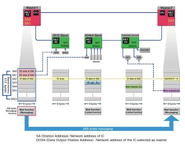
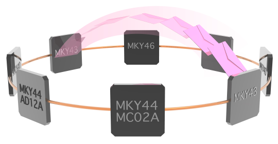
CUnet is a "multiple master and multiple slaves" remote I/O control network. Up to 64 CUnet ICs can be connected on the network, while masters and slaves constantly communicate automatically.
With CUnet ICs, master ICs and slave ICs both have 512 bytes of memory, and data is shared across the network, so all of the CUnet IC memory data is the same after one network cycle (data sharing). As a result, the CPU connected to a master IC can control the I/O of each slave just by reading and writing the master IC's memory. Network connection is made with multidrop wiring using RS-485; using a HUB IC (MKY02) allows T-type branching and wiring extension.
[Operation]
CUnet allows multi-master configuration and memory sharing. For this purpose, the following settings must be made.
OWN: The number of memory blocks a master IC will use, selectable by the master IC
SA (Station Address): Network address of each CUnet IC
DOSA (Data Output Station Address): The SA (Station Address) of the IC a slave selects as a master
[Data sharing (CUnet communication concept)]
Each CUnet IC contains a 512-byte shared memory, which consists of 64 blocks (1 block: 8 bytes). This memory consists of a "self-owned area" to which only the IC itself can write and an area where data from other CUnet ICs is copied. Data written to the "self-owned area" is immediately shared (copied) to the memory of all terminals by broadcast. As a result, the CPU connected to a master can grasp the state of other CUnet ICs just by reading the master IC's memory. Also, the number of blocks used in the master IC can be set freely. A slave IC uses its self-owned area only for input. This self-owned area is fixed at 1 block (8 bytes).
[Input operation of the slave]
In control of digital I/O, analog I/O, and positioning, a slave's input data is automatically written to the 1-block (8-byte) self-owned area, and all terminals share (copy) the input data. CUnet ICs come with filtering and smoothing functions, so these do not require CPU processing.
[Output operation of the slave]
Because CUnet is multiple-master, a slave must select the IC to be its master. The slave IC selects its master by DOSA (Data Output Station Address), and the data of the "self-owned area (SA)" of the selected master IC is output.
[Error identification function]
CUnet has a unique error identification function. Because CUnet is multiple-master, it can check its own communication for errors. When there is an error in communication with a slave, a CUnet IC that supports error identification*1 can check the register to find out how many errors occurred with which terminals.
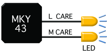
Also, the CUnet ICs with the error detection function have error notification pins. By connecting LEDs to them, for instance, one can check the error status visually.
It is also possible to detect errors immediately with interrupt function.
LCARE (Link CARE): If an error occurs with a terminal
MCARE (Member CARE): If an error occurs with the same terminal 3 times consecutively
*1 CUnet ICs that support error identification:
MKY43, MKY40, MKY44-IO32A, MKY44-AD12A, MKY44-AD16A, MKY44-AD16B,
MKY44-DA16A, MKY44-DA16B, MKY44-MC01A, MKY44-MC02A
Special functions
CUnet has a variety of special functions. Below are some of the most notable.
□Mail function (P2P data transmission)
CUnet ICs that support the mail function*2 can transfer up to 256 bytes of P2P (peer-to-peer) data. CUnet ICs that support the mail function have not only the usual 512 bytes of shared memory, but also 256-byte mail send buffers and mail receive buffers. They work as below.
- On the transmitting side, set the data in the mail send buffer to select the destination.
- On the receiving side, set the receive enable flag.
- On the transmitting side, set the send flag to start sending the mail data.
- When all data has been received, the receive complete flag is set.
In the mail function, data is sent 8 bytes per scan and collected in the recipient's buffer.
This makes it best for data transmissions that do not require speed.
This mail function can also be operated at the same time as data sharing and I/O control. Using the mail function does not change the CUnet cycle time.
*2 CUnet ICs that support the mail function:
MKY43, MKY40, MKY44-IO32A, MKY44-AD12A, MKY44-AD16A, MKY44-AD16B,
MKY44-DA16A, MKY44-DA16B, MKY44-MC01A, MKY44-MC02A
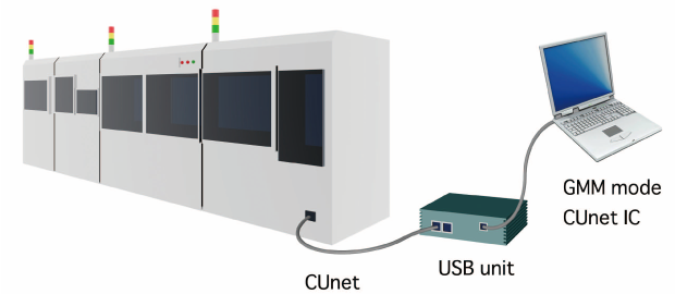
□GMM (Global Memory Monitor) function
“GMM function” is a function that enables monitoring the shared memory and register while operating the network.
It can be used with MKY43 and MKY40 (MEM mode).
In GMM mode, CUnet IC is not counted as a terminal that constitutes the network.
Since it is not recognized as a network terminal, checking can be done safely.
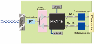
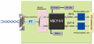
□Slave board block diagram
The figure below is a block diagram of typical CUnet slave board. As shown in the diagram, the board can be configured with simple circuit.
| The slave using MKY 46 | The slave using MKY 44 |
 |
 |