HLS network
Summary
HLS is a "one master and multiple slaves" open field network that can control digital I/O at Ultrahigh-speed, as a batch. Each master IC can be connected to up to 63 slave ICs, to control up to 2016 I/Os. HLS uses built-in protocol and automatic communication, making it easy to achieve high-speed control at up to 15 µs per node. Even analog control can be achieved with HLS, using units from our partner manufacturers.
"HLS Introduction Guide" and "HLS Technical Guide" can be downloaded from here.
HLS network devices
Learn about our devices for building HLS networks.
| Series name | Master (center) IC | Slave (satellite) IC | HUB-IC | |
|---|---|---|---|---|
| Type | MKY36 | MKY37 | MKY02 | |
| Package |  |
 |
 |
|
| Number of I/O | ― | 16DIN 16OUT | ― | |
| Supply voltage | 3.3 V (5 V tolerant) | 5.0 V | 3.3 V (5 V tolerant) | |
| Features | 16/8 bit bus Interface support |
No CPU needed Basic model Low power consumption |
No CPU needed T-type branching and wiring extension possible |
* Click the model or package photo of a product to see details.
HLS specifications
| ■Specifications | ||
| Communication method | HLS (Hi-speed Link System) Master/slave type polling method |
|
|---|---|---|
| Connection type | Multi-drop method (RS485) | |
| Communication speed | 12 Mbps/6 Mbps/3 Mbps (full-duplex/half-duplex) |
|
| Communication cable | Shielded cable of category 5 or higher | |
| Maximum number of connection node | 63 nodes | |
| Number of I/O control | 1 terminal: 16 IN, 16 OUT 63 terminals: 1008 IN, 1008 OUT |
|
| Communication distance | Communication speed | Maximum length of network |
| 12 Mbps | 100 m | |
| 6 Mbps | 200 m | |
| 3 Mbps | 300 m | |
| Topology | Bus (at using HUB: tree/star) | |
| Note: The communication distance above are approximate data, it may vary on its operating conditions. | ||
| ■Communication rate (in full-duplex communication) | |||
| 12 Mbps | 6 Mbps | 3 Mbps | |
|---|---|---|---|
| 2 nodes | 30.33 µs | 60.67 µs | 121.33 µs |
| 8 nodes | 121.33 µs | 242.67 µs | 485.33 µs |
| 16 nodes | 242.67 µs | 485.33 µs | 970.67 µs |
| 32 nodes | 485.33 µs | 970.67 µs | 1941.33 µs |
| 63 nodes | 955.50 µs | 1911.00 µs | 3822.00 µs |
| Note: Half-duplex communication achieves approx. twice the displayed values | |||
| ■Communication range when using a HUB | |||
| 12 Mbps | 6 Mbps | 3 Mbps | |
| HUB-1 | 200 m | 400 m | 600 m |
| HUB-2 | 300 m | 600 m | 900 m |
| HUB-3 | 400 m | 800 m | 1200 m |
| HUB-4 | 500 m | 1000 m | 1500 m |
| HUB-5 | 600 m | 1200 m | 1800 m |
| HUB-6 | 700 m | 1400 m | 2100 m |
| HUB-7 | 800 m | 1600 m | 2400 m |
| Note: Approximately twice the described value in half-duplex communication | |||
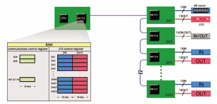
HLS network configuration
HLS is a remote I/O control network of “one master and multiple slaves.”
Master and slave ICs communicate automatically with each other and the system can connect up to 63 slave ICs.
An HLS master IC contains memory for a register for I/O control for each slave IC, and for a communication control register.
The CPU connected to the master IC can control the I/O of each slave just by reading and writing this memory.
Communication control such as communication start and I/O change interrupt handling also can be controlled just by reading and writing the memory.
Although multi-drop wiring using RS485 is utilized for the connection, branching and wiring extension are also possible by using HUB-IC (MKY02.)
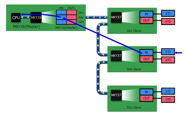
■■ HLS read and write operation ■■
----------- Read operation -----------
- I/O input data is automatically read into the memory in the master IC, constantly renewing it the latest state.
- If the CPU needs to get the input data of slaves individually:
The CPU can get current slave input data just by reading the memory in the master IC.
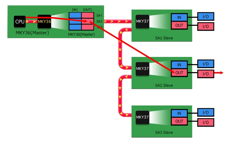
----------- Write operation -----------
- If the CPU needs to output individual data to slaves:
The CPU can output current output data to slave ICs just by writing data to the memory in the master IC.
■■ Error identification function ■■
HLS has a unique error identification function.
When there is an error in communication with a slave,
the master IC MKY36 can check a register to
find out how many errors occurred with which slaves.
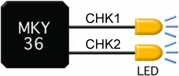
Also, the master IC has error notification pins (CHK1,CHK2.)
By connecting LEDs to them,
for instance, one can check the error status visually.
It is also possible to detect errors immediately with interrupt function.
CHK1: If an error occurs with a slave in 1 scan
CHK2: If an error occurs with the same slave 3 times consecutively
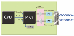
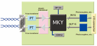
□Board block diagram
The figure below is a typical block diagram of HLS board while in full-duplex. As shown in the diagram, the board can be configured with simple circuit.
| Master | Slave |
 |
 |
[Reference] Hot-swapping is supported if the recommended pulse transformer is used.
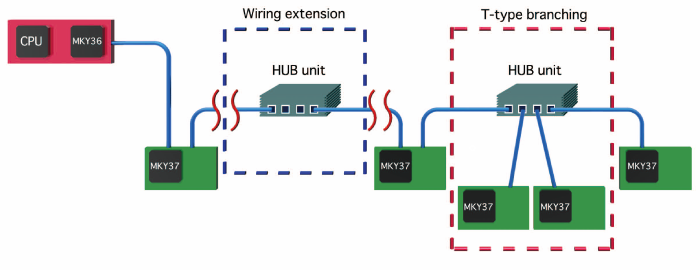
■■ Wiring extension and T-type branching ■■
HLS is a network configured with multi-drop connection (RS485.)
Sometimes networks need to be expanded. That is why we have the MKY02 HUB-IC.
This allows wiring extension and T-type branching.