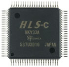
MKY33 (Discontinued products)
 |
■Discontinued October 31, 2021 |
|
|
HLS master IC, 5 V The MKY33 is a center IC for the Hi-speed Link System (HLS), which supports a 1:N network configuration. |
||
Features
Basic functions
- (1)Can connect to a CPU that has either a 16-bit bus or an 8-bit bus
- (2)Can connect to a CPU that is either big endian or little endian
- (3)Has a dynamic arbiter to make access from the user CPU faster
- (4)Supports the standard baud rates of 12 Mbps, 6 Mbps, and 3 Mbps and baud rates governed by external clocks
- (5)Supports full-duplex and half-duplex communication modes
- (6)Supports installation of two networks (has two RXD pins)
- (7)Owns a 1,280-byte address area (000H through 4FFH)
- (8)Supports a single 5.0 V power supply to a 0.8 mm–pitch, 84-pin QFP
User-support functions
- (1)Recognizes individual satellite ICs and the MKY33 link status (connection status and error occurrence)
- (2)Can acquire data on expanded function other than Di data (other than the I/O input pin data of satellite ICs)
from individual satellite ICs - (3)Can check network quality
- (4)Can detect terminal errors and recognize poor environments
Operation
All MKY33 operation is performed by read access and write access to the registers and areas assigned to the memory map as follows. It is very simple. See the figure.
- (1)Use 00H data to initialize all of the memory areas of the MKY33 connected
to the memory area of the user CPU. - (2)Write the initial data output from the I/O pin of the terminal to the Do area
of the memory of the MKY33. - (3)Write the final satellite (FS) value to the system control register (SCR) of
the MKY33. This starts the HLS scan. - (4)For a user-system program to reference the input state of the I/O pin of
the terminal, read the Di area of the memory of the MKY33. - (5)For a user-system program to change the output state of the I/O pin of
the terminal, write to the Do area of the memory of the MKY33. - (6)For a user-system program to use the user-support functions of the MKY33
or recognize the HLS state, read from or write to the memory address of
the MKY33 assigned to the function.
In the preceding list, steps (1) through (3) are for initialization of the MKY33. Only steps (4) and (5) are for basic operation. Step (6) is for applied operation. Such applied operation powerfully supports the innovation of user-system programmers and system engineers so that user systems can use the functions of HLS more effectively.
◆Note:
You can skip step (2) if you do not need to set initial values for the I/O pin output of the terminal. In almost all cases, when a user system is first started up, the I/O pin state of the terminal is the reset default value that satellite ICs have. Also, the reset default values of satellite ICs are the same as initialization by 00H in the MKY33 memory area in step
(1). Therefore, you can skip step (2) in almost all cases.
Specification of MKY33
Main specification
| Item | Specification |
|---|---|
| Communication method | HLS communication method |
| Operating ambient temperature | -40 to +85°C |
| Package | QFP |
| Package dimension | 22.9 x 22.9 x 2.9 mm |
| Communication rate | 3/6/12 Mbps |
| Storage temperature | -55 to +150°C |
| Pin count | 84 pins |
| Pin pitch | 0.8 mm |
Main electrical characteristics
| Item | Conditions | Minimum | Standard | Maximum |
|---|---|---|---|---|
| Power supply voltage | 4.5 V | 5.0 V | 5.5 V | |
| Average operating current | VI = VDD or VSS f = 50MHz output open |
- | 40 mA | 80 mA |
| Operating frequency of external input |
Input to the XI pin | - | 48 MHz | 50 MHz |
